Utilisation du port de bypass
Le port de bypass (Backup) est une interface à direction automatique qui ne nécessite aucun réglage manuel. Il peut être utilisé pour :
- 🔌 Charges électriques → sortie (alimentation)
- ☀️ Micro-onduleur PV → entrée (production)
1. Détection automatique de l’appareil
Le système identifie automatiquement le type de connexion en fonction de la direction de puissance + durée :
| Type | Condition de détection |
|---|---|
| Charge | Puissance de sortie supérieure à 30 W et maintenue pendant plus de 20 secondes |
| Micro-onduleur | Puissance d’entrée supérieure à 30 W et maintenue pendant plus de 5 secondes |
- En mode hors réseau, si la puissance du port bypass est de 0 W, le système conserve le dernier état détecté
- Après redémarrage, le mode par défaut est charge
2. Comportement selon les scénarios
Le comportement dépend de :
- la présence du réseau (mode connecté au réseau / hors réseau)
- le type d’équipement connecté (charge ou micro-onduleur)
La capacité du port bypass dépend du nombre de batteries installées. Une seule unité peut ne pas atteindre la puissance maximale indiquée. Pour des puissances plus élevées, ajouter des packs batterie.
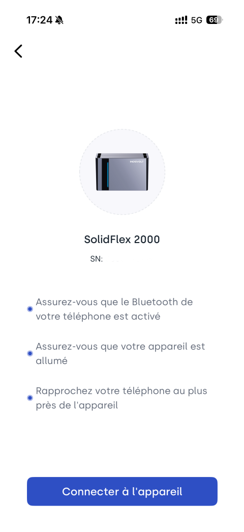
Configuration minimale recommandée :
- 1 × SolidFlex 2000 + 2 × SFA1800
- 1 × PowerFlex 2000 + 1 × PFA2000
2.1 Mode connecté – charge
La charge est alimentée par le réseau électrique ou par l’onduleur du système.
Plage de puissance :
- Puissance ne dépassant pas 3600 W : fonctionnement normal
- Puissance supérieure à 3600 W (courant ne dépassant pas 16 A) pendant plus de 5 secondes : protection déclenchée, désactivation du port bypass, rétablissement automatique après 15 minutes
Protection batterie :
- arrêt de la décharge lorsque le SOC atteint 5 %
2.2 Mode connecté – micro-onduleur
L’énergie du micro-onduleur alimente la charge et charge la batterie. L’excédent peut être injecté au réseau dans la limite autorisée.
Plage de puissance :
- Puissance ne dépassant pas 2400 W : fonctionnement normal
- Puissance supérieure à 2400 W pendant plus de 30 secondes : déclenchement de la protection, le port de bypass est coupé, rétablissement automatique après 15 minutes
Limitation d’injection réseau :
- Si la puissance dépasse la limite d’injection de 10 % pendant plus de 30 secondes, le système coupe le bypass en priorité et rétablit après 15 min
2.2.1 Gestion énergétique en mode connecté
En mode connecté au réseau, le système répartit automatiquement l’énergie selon le mode énergétique sélectionné, en suivant toujours ce principe : priorité à l’alimentation des charges domestiques ou à la charge de la batterie, puis injection sur le réseau en dernier. Selon le mode choisi, la priorité entre les charges et la batterie peut varier.
Le micro-onduleur est utilisé comme source photovoltaïque complémentaire, tandis que le PV direct reste la source principale.
Gestion du surplus d’énergie
Lorsque la production dépasse la consommation (charges satisfaites + batterie pleine) :
| Le surplus dépasse-t-il la limite d’injection réseau ? | Action du système |
|---|---|
| Non | Le surplus est injecté directement sur le réseau |
| Oui | Le système ajuste automatiquement pour éviter toute surcharge : - Si la production du micro-onduleur est trop élevée (puissance du micro-onduleur supérieure à la limite d’injection) : le port de bypass est déconnecté - Si la puissance du micro-onduleur est dans la limite mais que la production PV directe entraîne un dépassement : réduction de la puissance PV directe |
Réglage de la limite d’injection :
INDEVOLT App → Appareil →→ Paramètres De Puissance → Limite d’injection
Mode 1 : Autoconsommation
- Le micro-onduleur alimente d’abord les charges
- Puis charge la batterie
- Une fois les charges satisfaites et la batterie pleine, l’injection sur le réseau se fait selon les règles du surplus d’énergie
Mode 2 : Plan de charge/décharge
(1) Charge
-
A. Recharge solarire uniquement
- Le micro-onduleur charge la batterie en priorité
- Puis alimente les charges
- Une fois la batterie pleine et les charges satisfaites, l’injection sur le réseau se fait selon les règles du surplus d’énergie
-
B. Recharge solarire + réseau
- Priorité au PV direct pour la batterie :
- Lorsque la production PV est suffisante pour la charge (supérieure à la puissance de charge définie par le mode actuel) : la batterie est chargée par le PV direct, et le micro-onduleur alimente en priorité les charges
- Lorsque la production PV est insuffisante : le micro-onduleur complète en priorité la charge de la batterie, et le surplus d’énergie est ensuite envoyé aux charges
- Une fois la batterie complètement chargée, la production du micro-onduleur alimente en priorité les charges
- Lorsque la batterie est pleine et que les charges sont satisfaites, l’injection sur le réseau suit les règles du surplus d’énergie
- Priorité au PV direct pour la batterie :
(2) Décharge
- Micro-onduleur alimente d’abord les charges
- Puis charge la batterie
- Une fois les charges satisfaites et la batterie pleine, l’injection sur le réseau se fait selon les règles du surplus d’énergie
Mode 3 : Contrôle en temps réel
(1) Veille / Charge
- La production du micro-onduleur charge la batterie en priorité
- Une fois la batterie pleine :
- Si la puissance de production ne dépasse pas 50 W : maintien de l’état actuel pour alimenter la consommation propre du système
- Si la puissance de production dépasse 50 W pendant plus de 30 secondes : déconnexion du port de bypass et réduction de la puissance PV directe afin de ramener la production totale en dessous de 50 W
(2) Décharge
- La production du micro-onduleur alimente en priorité les charges
- Puis la batterie est chargée
- Une fois la batterie pleine :
- Si la puissance de production ne dépasse pas la puissance de décharge définie + tolérance : fonctionnement normal du système
- Si la puissance de production dépasse la puissance de décharge définie + tolérance : déconnexion du port de bypass
Tolérance = 50 W ou 10 % de la puissance définie (la valeur la plus élevée étant retenue)
Exemples :
- Puissance de décharge définie à 400 W → protection déclenchée au-delà de 450 W
- Puissance de décharge définie à 800 W → protection déclenchée au-delà de 880 W
2.3 Mode hors réseau – charge
Après coupure du réseau, les charges sont alimentées par l’onduleur du système.
Plage de puissance :
- Puissance inférieure ou égale à 2400 W + 2 % (2448 W) : fonctionnement stable du système
- De 2448 W à 2640 W : surcharge supportée pendant 30 secondes
- De 2640 W à 3000 W : surcharge supportée pendant 15 secondes
- Supérieure à 3000 W : surcharge supportée pendant 100 millisecondes
- Si la capacité de surcharge est dépassée : déconnexion du port de bypass, rétablissement automatique après 15 minutes
2.4 Mode hors réseau – micro-onduleur
-
EMS inférieur à 1.01.05 ❌ Micro-onduleur non pris en charge (bypass désactivé pour protection)
-
inférieur à 1.01.05 ✅ micro-onduleur pris en charge
- Plage de puissance : 30 W à 1200 W
- Lorsque le SOC est inférieur à 3 %, l’onduleur du système cesse temporairement de réagir à l’entrée du micro-onduleur, mais le port de bypass reste actif ; lorsque le SOC repasse au-dessus de 3 %, le système reprend automatiquement la prise en charge du micro-onduleur.
3. Activation / désactivation du bypass
| État du réseau | Méthode |
|---|---|
| Normal | App / Bluetooth |
| Anormal | Bluetooth uniquement |
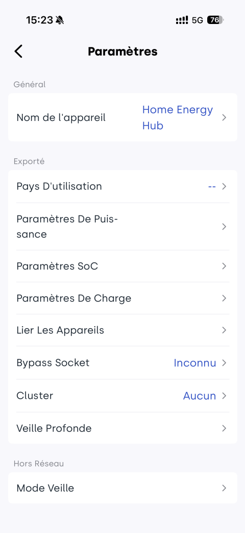
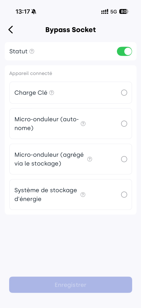
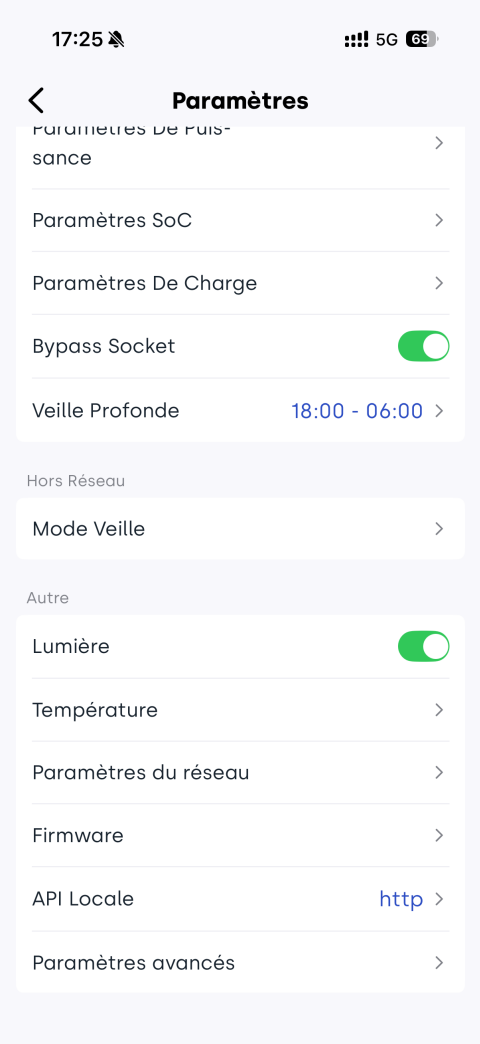
Méthode 1 : Configuration à distance via l’application (réseau normal)
App → Appareil → ![]() → Bypass Socket → Activer → sélectionner le type d’appareil
→ Bypass Socket → Activer → sélectionner le type d’appareil
Méthode 2 : Connexion locale via Bluetooth (sans réseau)
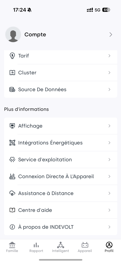
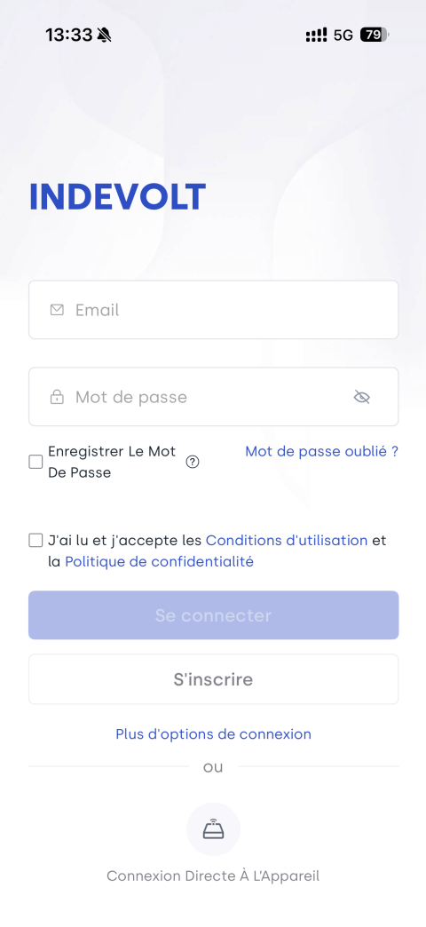
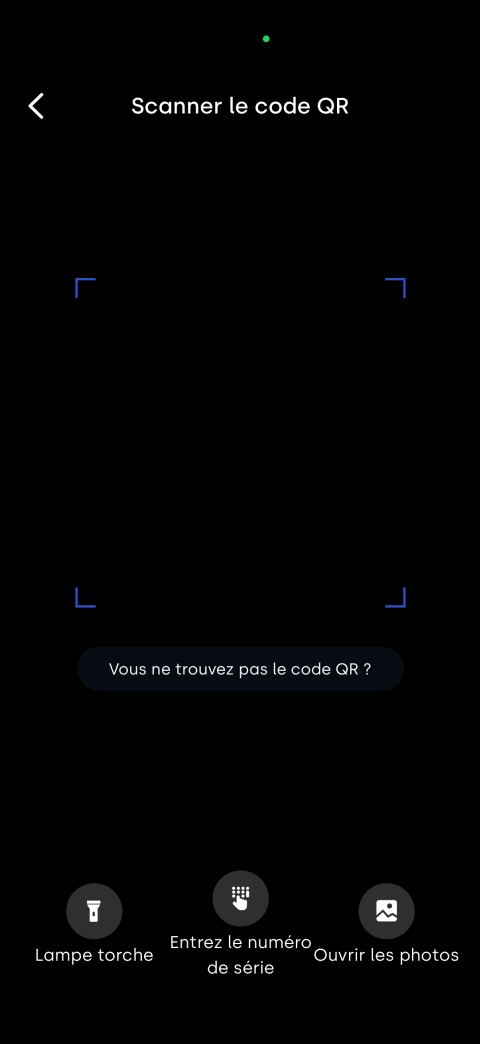
App → Profil / Connexion au compte → Connexion Directe À L'Appareil → Scanner le code QR → Connecter à l'appareil → ![]() → Bypass Socket → Activer
→ Bypass Socket → Activer
Remarque en mode hors réseau
Si le réglage de mise en arrêt en mode hors réseau est activé et que le compte à rebours d’arrêt est atteint, l’appareil passe en mode arrêt et le port de bypass est automatiquement désactivé. Il peut être réactivé selon les étapes suivantes :
Réactivation :
- Appui sur le bouton d’alimentation
- Activation via App ou Bluetooth selon l’état réseau