Quick Start
This document applies to SolidFlex 2000 / PowerFlex 2000 energy storage devices and provides a complete workflow from unboxing to first-time operation. It covers pre-installation checks, device installation, initial startup, and adding the device to the app.
Before proceeding, please read Safety Information carefully to ensure safe operation.
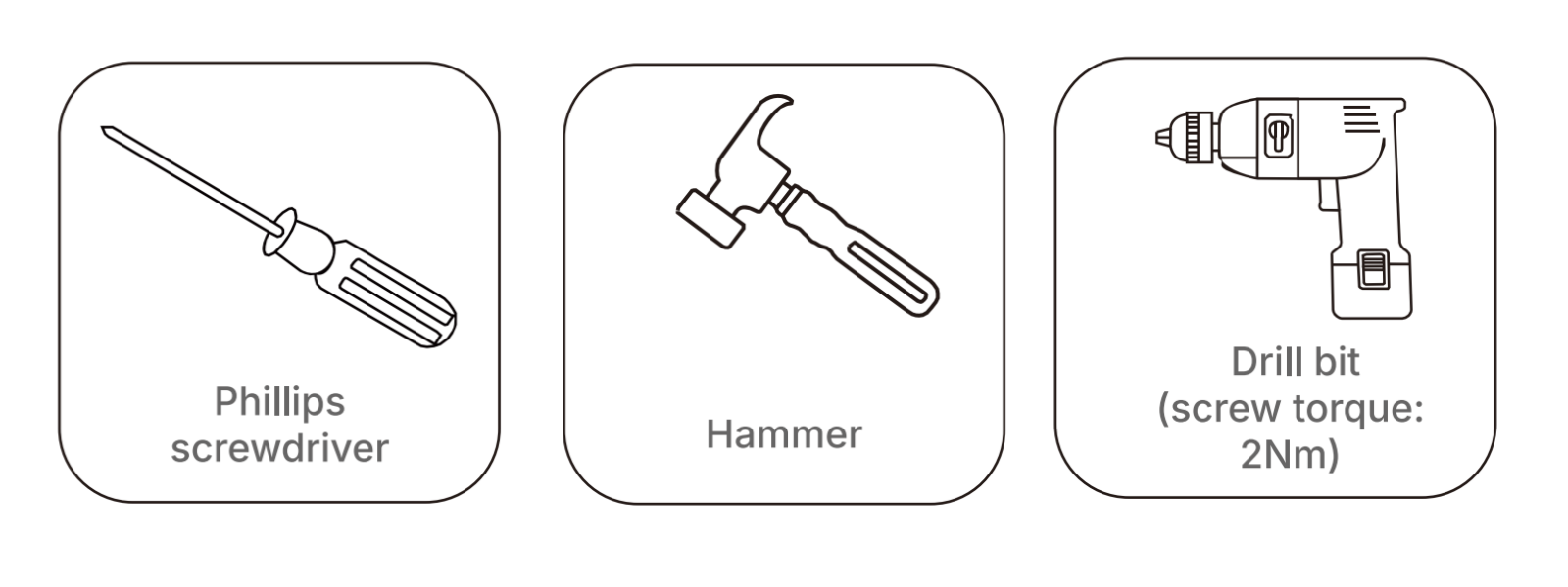
Required Tools
Before installation, please prepare the following tools:
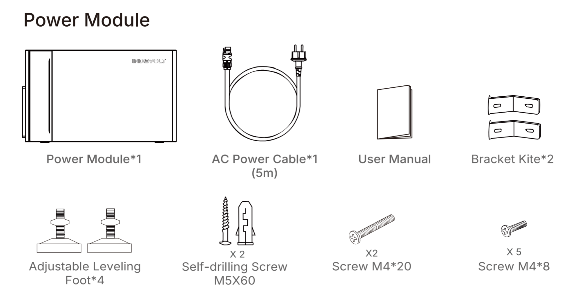
Unboxing & Packing List
-
Ensure the packaging is intact and undamaged.
-
Open the box and remove the device and accessories one by one.
-
Check all items against the packing list to confirm there are no missing or damaged parts.
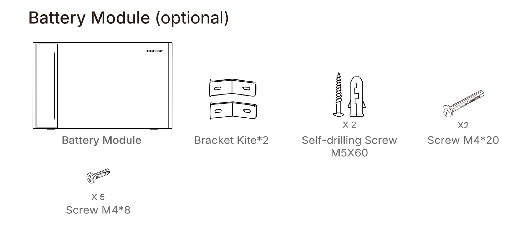
If you also purchased battery modules, please check against the following list:
Installation Instructions
- Do not install the module in areas exposed to direct sunlight, near open flames, or close to flammable or explosive materials.
- Ensure the installation location is protected from potential hazards such as flooding.
- Recommended for use at altitudes below 2000 meters.
- Ensure good ventilation for proper heat dissipation.
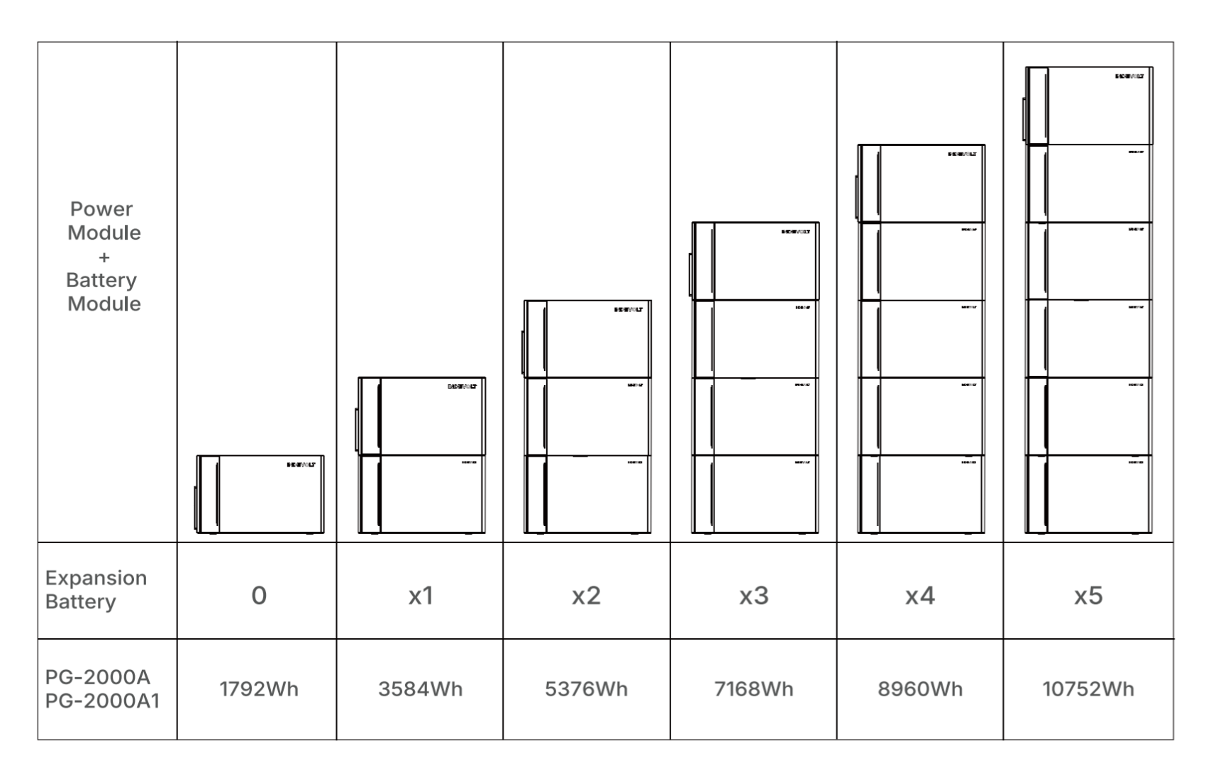
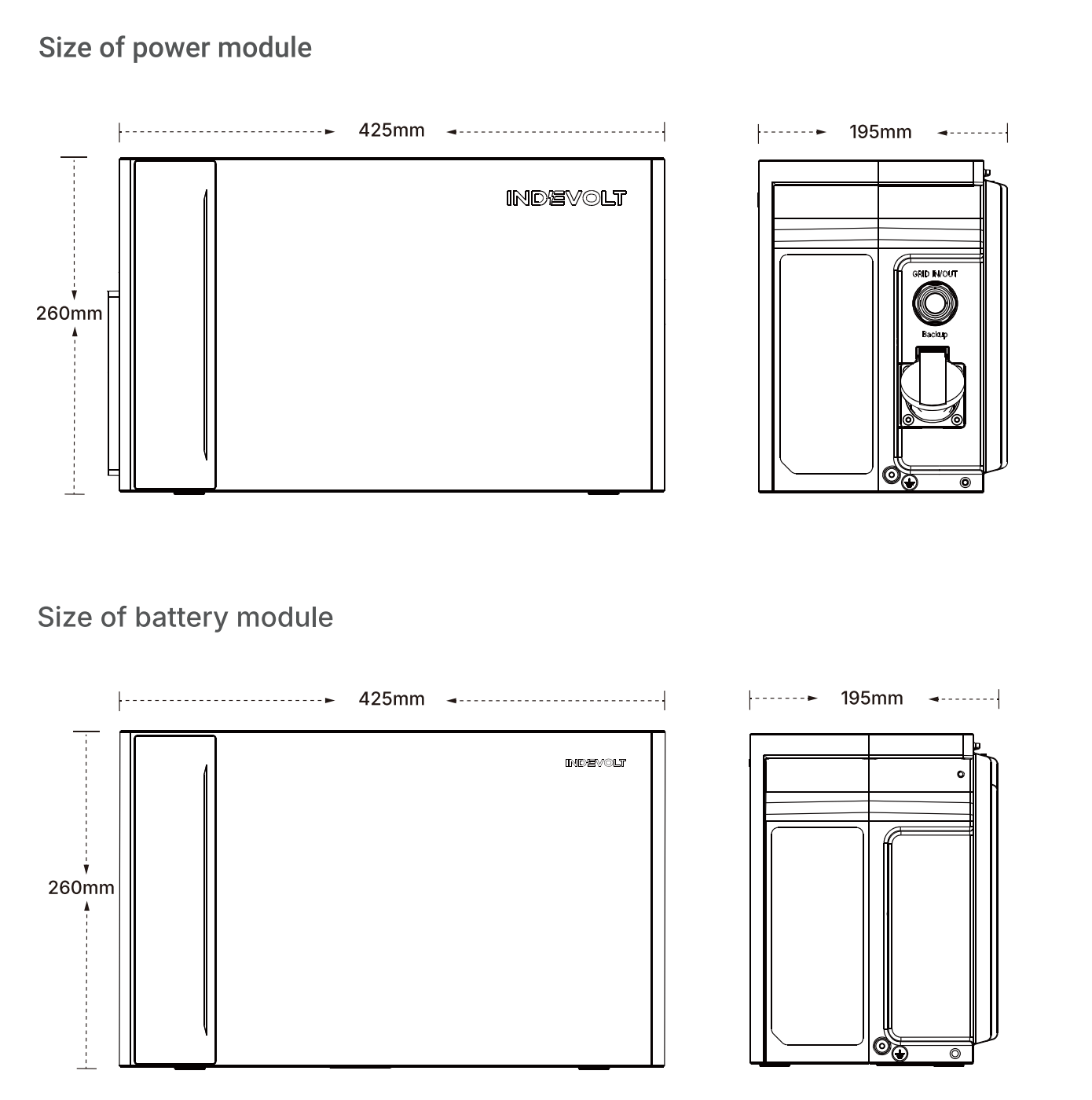
Step 1: Measure the distance
Calculate the required installation space based on your actual configuration, ensuring sufficient clearance for heat dissipation and electrical safety.
Step 2: Secure the Device
The following example uses 1 power module + 2 battery modules:
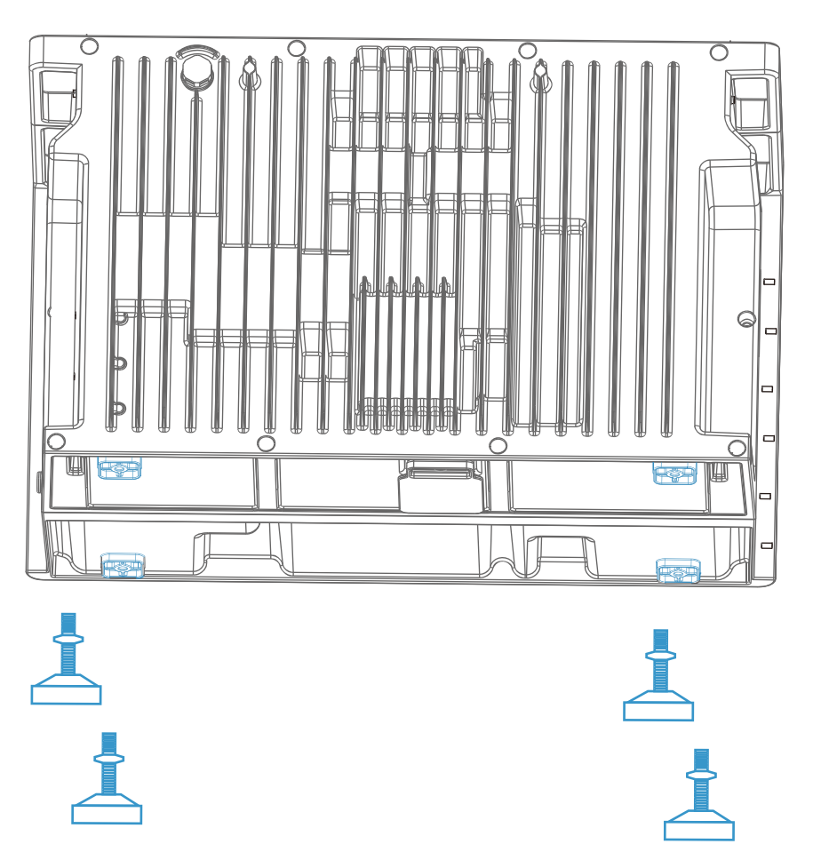
-
Install four support feet on the bottom of the lowest expansion battery module.
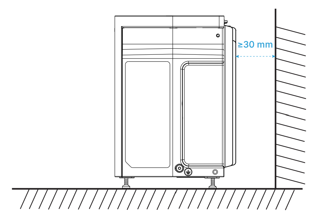
-
A minimum clearance of 30 mm must be maintained at the rear of the device(heatsink area) to ensure adequate ventilation and efficient heat dissipation.
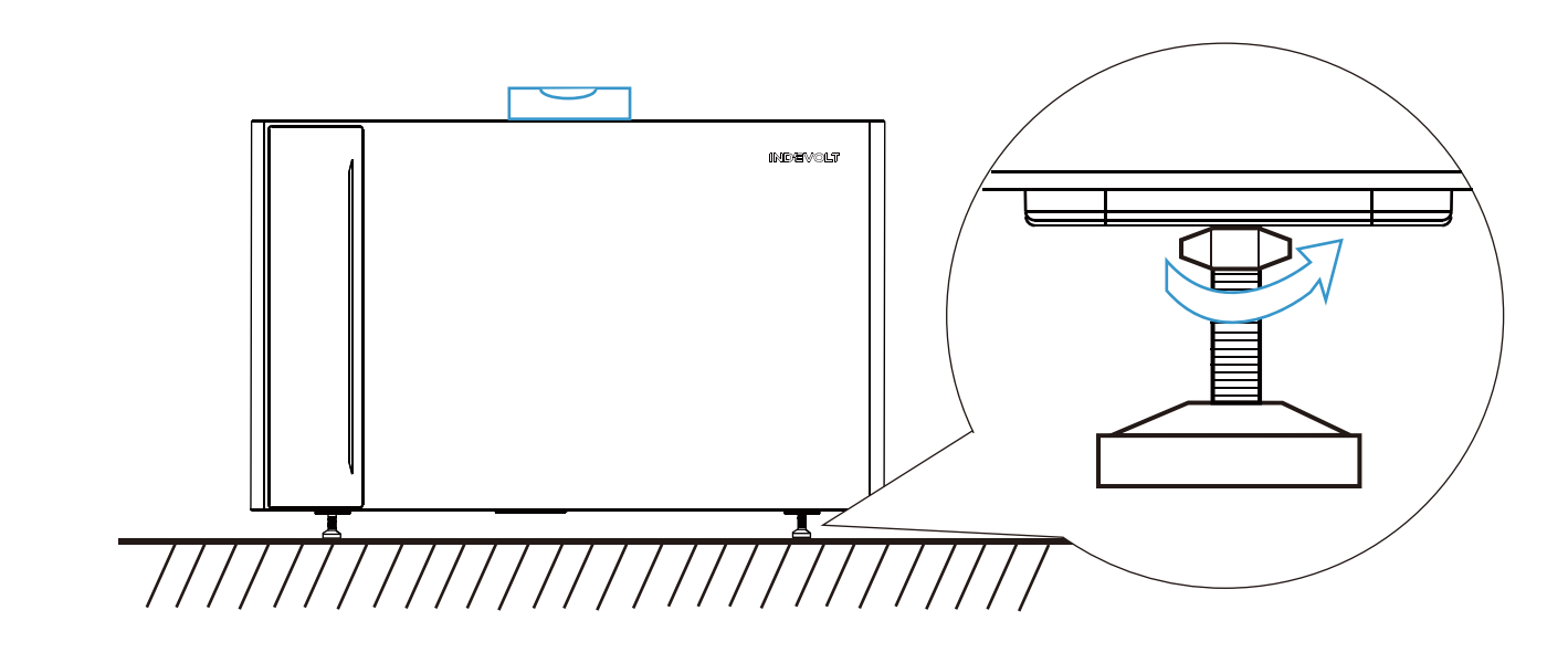
-
Adjust the four support feet to level the device. Use a spirit level for calibration.
-
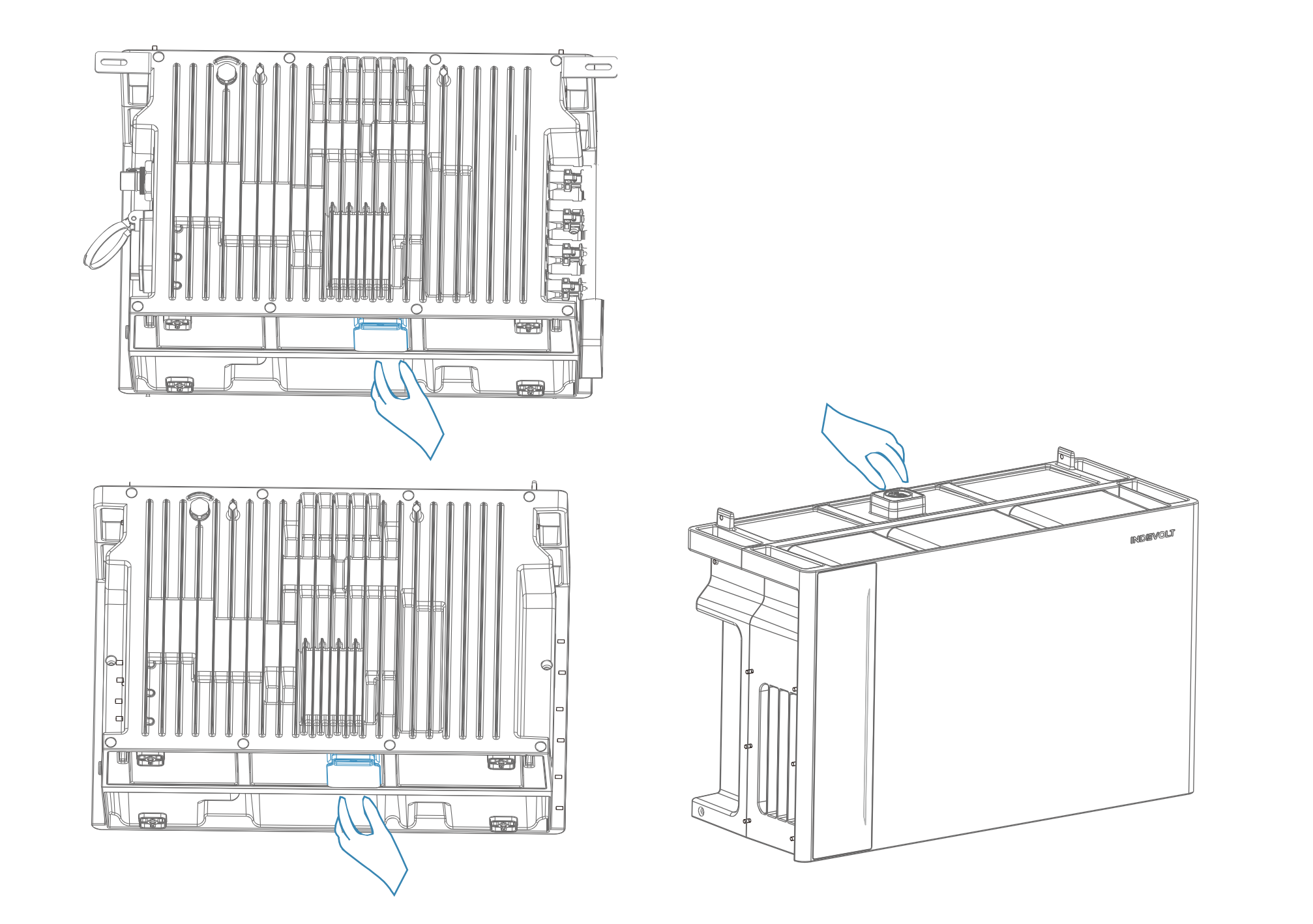
Remove the protective caps from:
- The bottom of the power module
- The top and bottom of the middle battery module
warningDo not remove the protective caps of the bottom expansion battery module, as this may cause device damage.
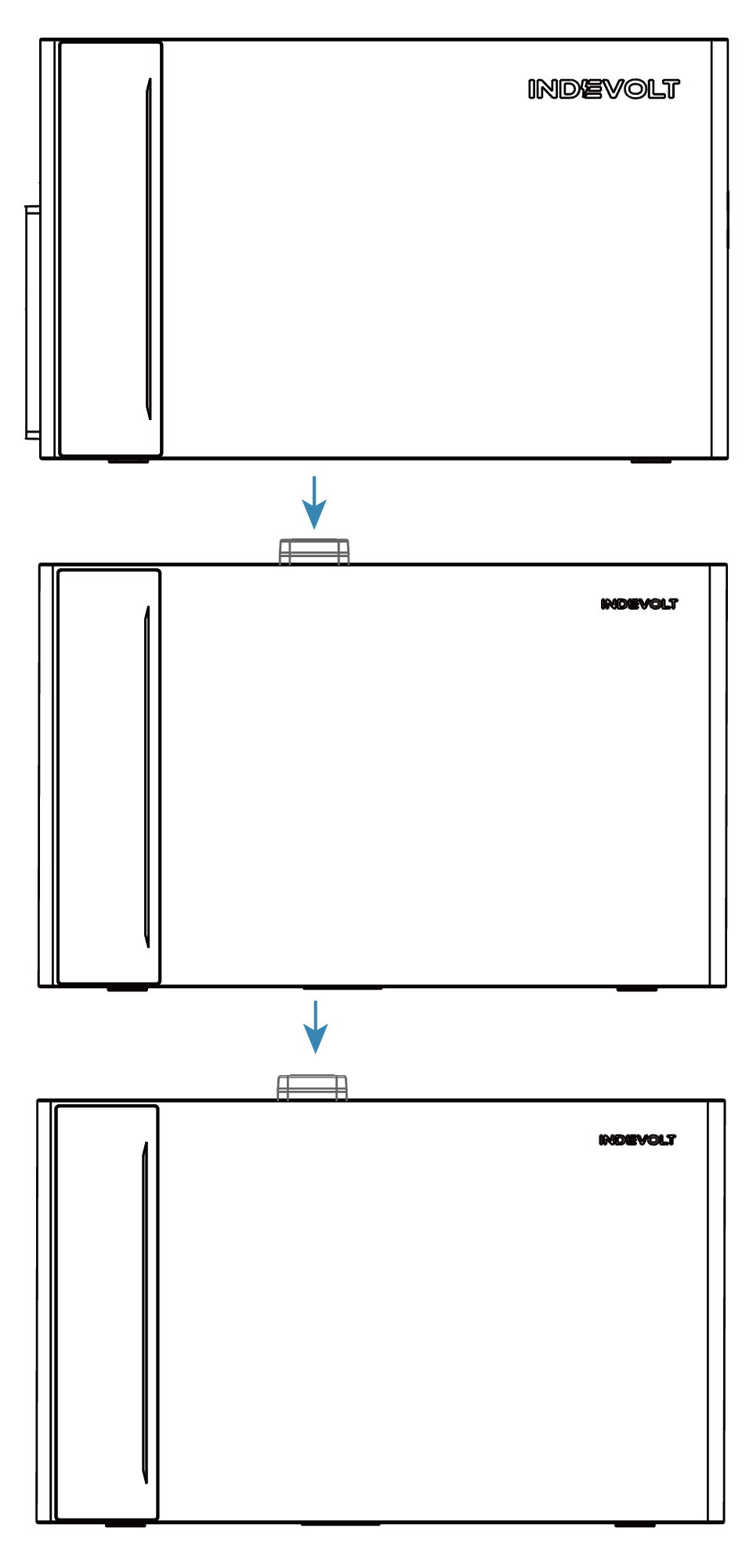
-
Align the expansion battery modules with the corresponding connectors and stack them upward one by one. Install the power module on top.
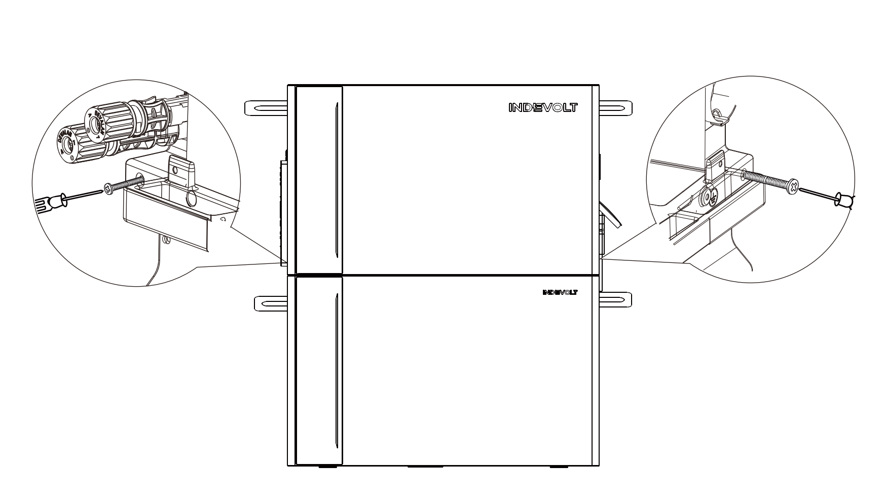
-
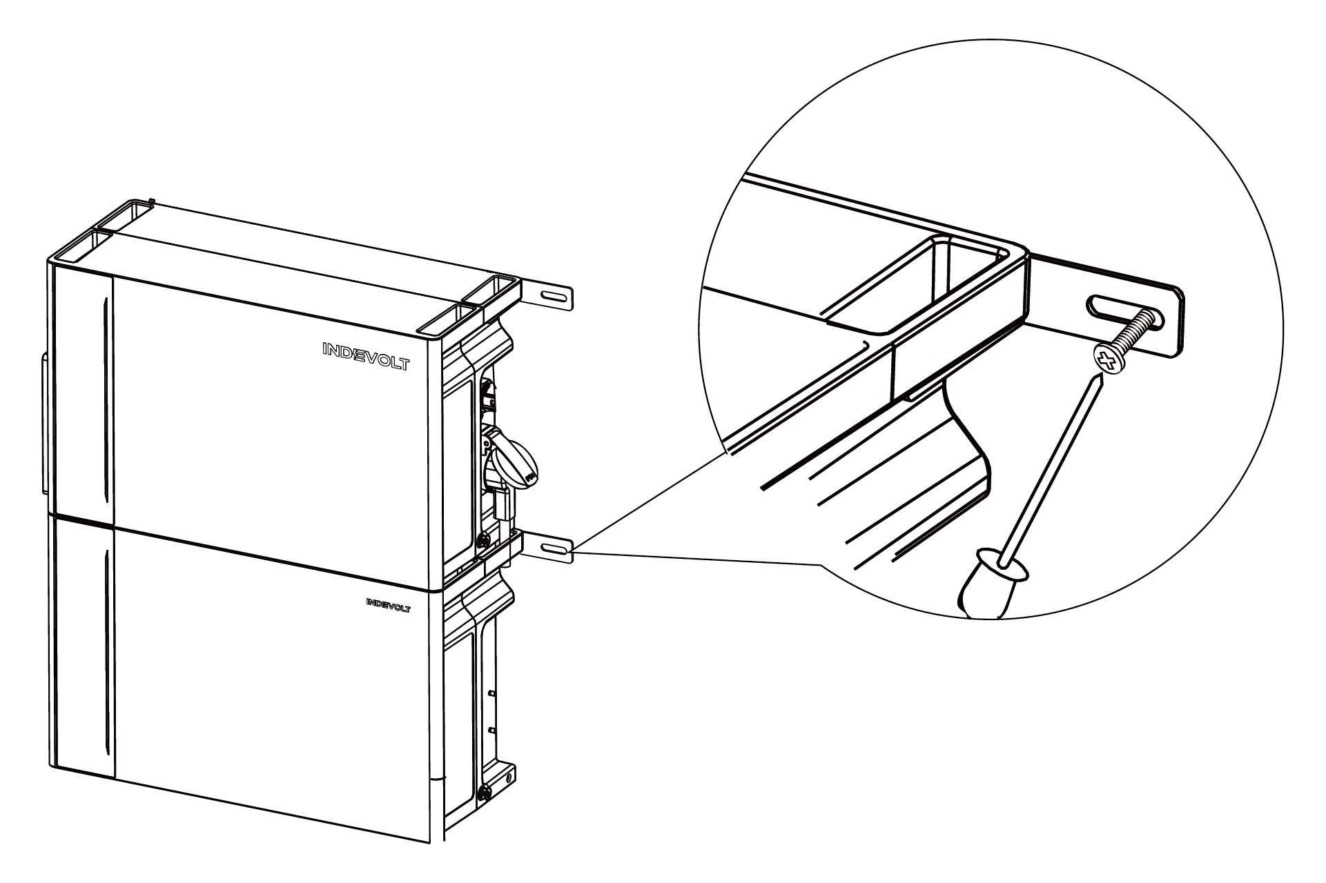
Use M4 Phillips screws to install the L-shaped wall mounting brackets on both sides of the first expansion battery module beneath the power module.
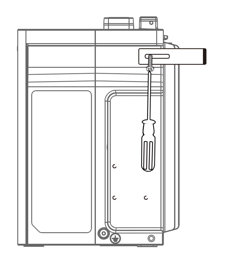
-
After stacking the power and battery modules, secure them together using M4 Phillips screws.
-
Mark drilling positions on both sides of the wall. Drill holes using an Ø8 mm drill bit to a depth of approximately 60 mm.
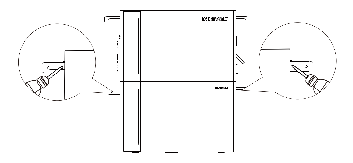
-
Insert the plastic expansion sleeves (for M5×60 self-tapping screws) into the holes with a hammer, then tighten the screws with a Phillips screwdriver to firmly secure the L-shaped wall brackets to the wall.
This product features a built-in dual isolation transformer that complies with relevant safety requirements. There is no need to measure the grounding insulation resistance of the PV array or test array fault currents.
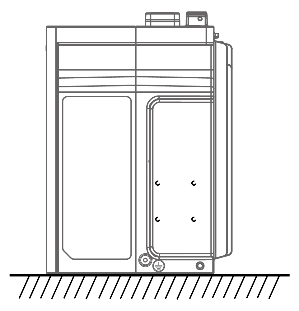
The main unit must be connected to a grounded power outlet to prevent electric shock risks. If a grounded outlet is unavailable, the device enclosure must be properly grounded. The grounding point is shown below.
Electrical Connections
- Installation of the AC grid connection must comply with local regulations. If beyond permitted limits, consult a qualified electrician.
The following example illustrates a standard configuration with four solar panels.
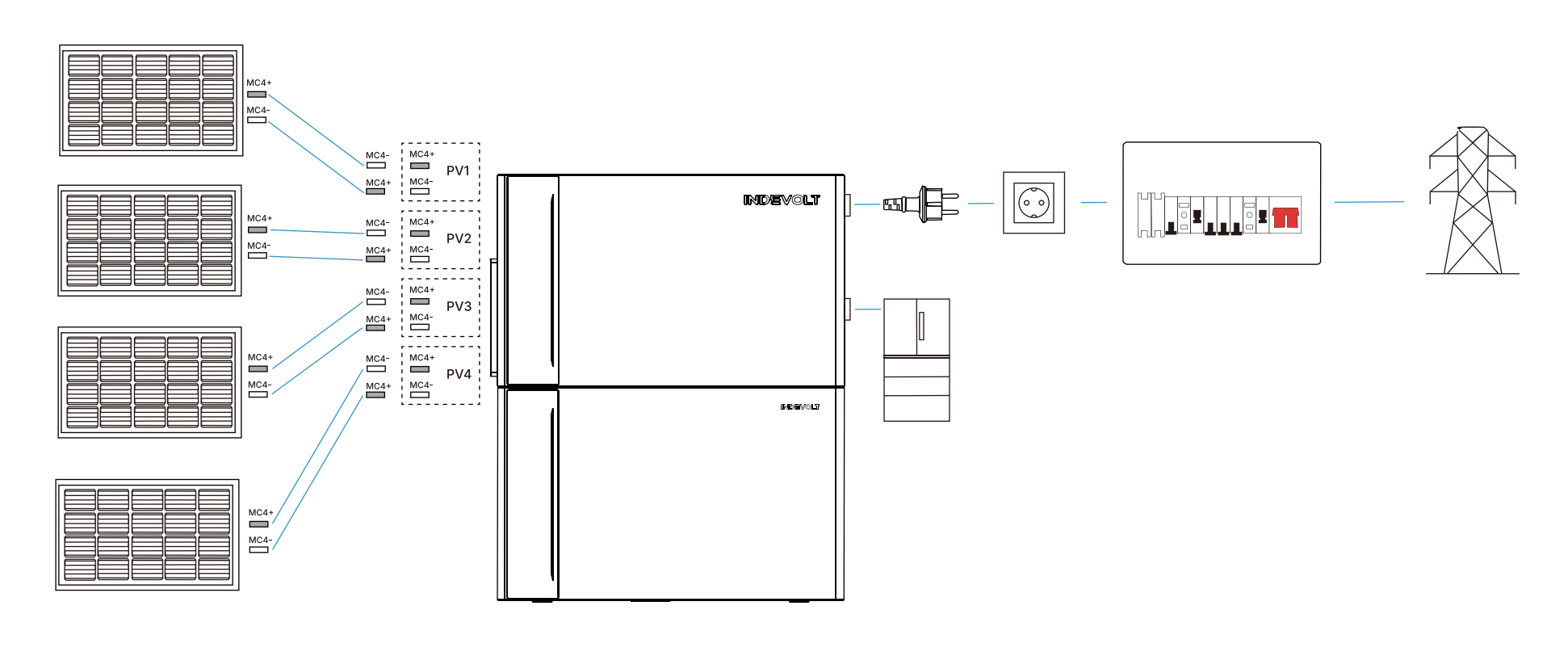
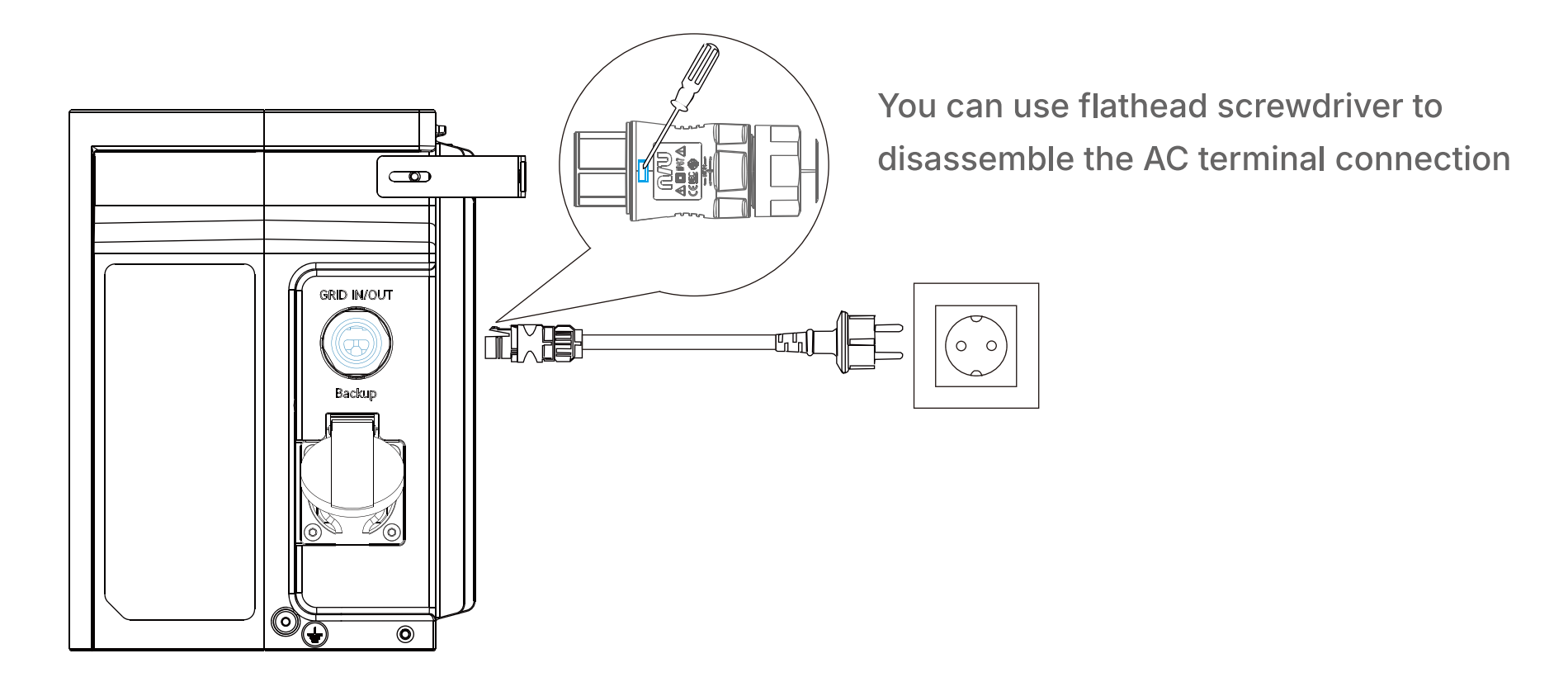
Step 1: Connect to the Grid
- Use the supplied power cable with safety plug (5 meters).
- Connect one end of the cable to the GRID IN/OUT port on the main unit.
- Plug the other end into a household or on-site power outlet.
Step 2: Connect Solar Panels
The ECO model does not include PV ports and does not apply to this step.
Use PV extension cables to connect the positive and negative outputs of each solar panel group to the corresponding PV input ports on the main unit (labeled PV1, PV2, etc.).
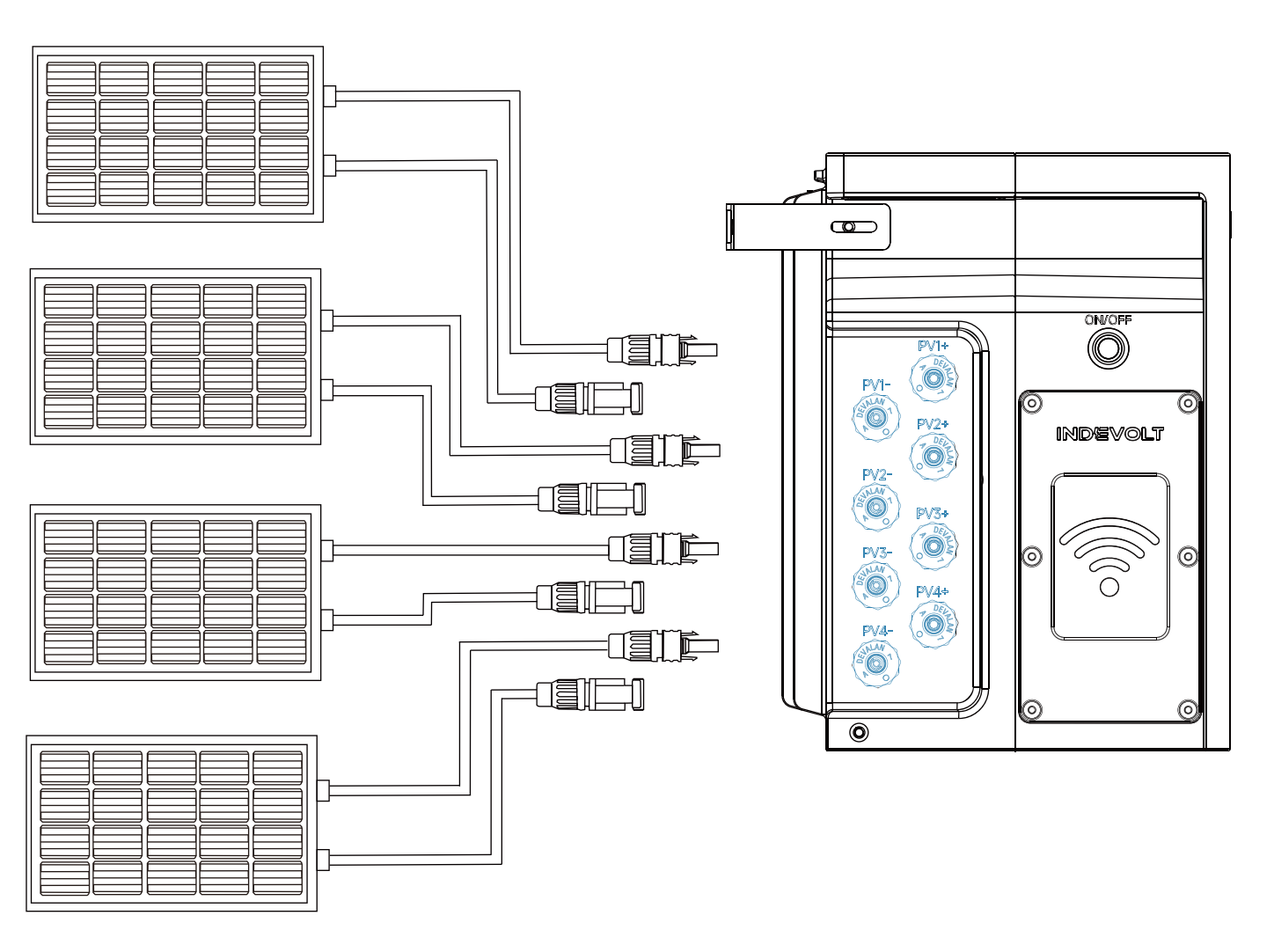
Do not connect two or more solar panels in series, as this may cause the input voltage to exceed 60V and damage the device.
If the main unit encounters a fault, the system will automatically attempt recovery within 15 minutes. If recovery fails, professional after-sales service is required. System functionality will only be restored after confirmation by authorized service personnel.
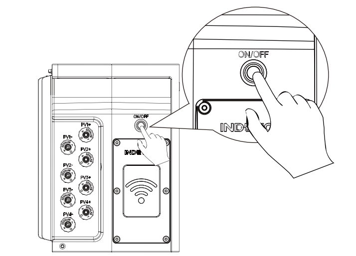
Power On
Locate the ON/OFF button on the left side of the main unit and press and hold for 2 seconds.
When the unit starts, the blue LED indicator on the front panel will illuminate with an animation spreading outward from the center.

Using the App
With the INDEVOLT App, you can:
- Monitor real-time device status and current power
- Check battery level and charge/discharge status
- View daily/weekly/monthly/yearly energy generation and consumption statistics
- Configure energy strategies, schedules, and perform firmware upgrades
📥 For first-time use, please complete the App download, account registration, and device setup.