Multi-Position CT Monitoring for Three-Phase Meters
In a three-phase system, each of the L1, L2, and L3 lines is typically equipped with a CT to measure the overall power and energy data of the system.
CTs are not limited to the three phase lines and can be installed at different system points such as PV, grid, load, and battery, enabling simultaneous monitoring of energy flows across the system.
1. Supported Meters
| Brand | Model |
|---|---|
| INDEVOLT | SMD3 |
| SOLARMAN | MR3-D5-WR MR3-D4-WE-B MR3-D5-W MR3-D4-WRE-B |
| Shelly | Shelly 3EM Shelly Pro 3EM-400 Shelly Pro 3EM-3CT63 |
2. CT Position
Different CT positions result in different measured data.
| CT Position | Corresponding Data | Typical Use Case |
|---|---|---|
| PV side | PV generation power | Monitor solar generation |
| Grid side | Import / export power (depends on direction) | Monitor grid interaction (anti-backflow / import-export monitoring) |
| Load side | Consumption power | Monitor load consumption |
| Battery side | Charge / discharge power | Monitor energy storage status |
CTs installed at different positions provide different measurements at the same time. Together, these values reflect the overall system operation.
3. CT Installation Direction
The arrow on the CT housing indicates the reference direction of current flow. An incorrect installation direction will not damage the device, but it will invert the power polarity.
For example, importing power from the grid may be displayed as exporting to the grid, and battery charging may appear as discharging.
If abnormal power direction readings occur, check the following:
- Whether the CT is installed in the reverse direction
- Whether the CT direction setting in the app is correct
If the physical installation direction of the CT cannot be adjusted easily, the direction can also be corrected in the app settings.
4. App Configuration
4.1 Set CT Position
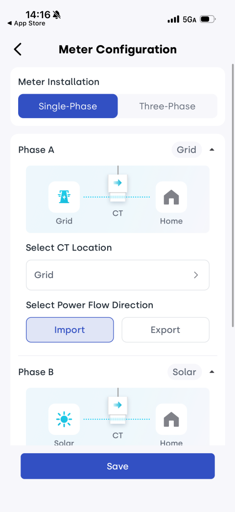
- Go to the meter settings page and select Meter Configuration > Single-phase System.
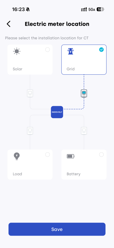
- Assign each of the three CTs to its actual installation position (Solar, Grid, Load, or Battery).
- Set the CT direction according to the actual arrow orientation. Use the diagrams to verify whether the direction matches the real installation.
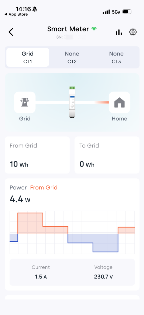
After configuration, you can view the corresponding data for each CT on the meter page, such as power, energy, current, and voltage.
4.2 Set Micro Storage Load Source (Optional)
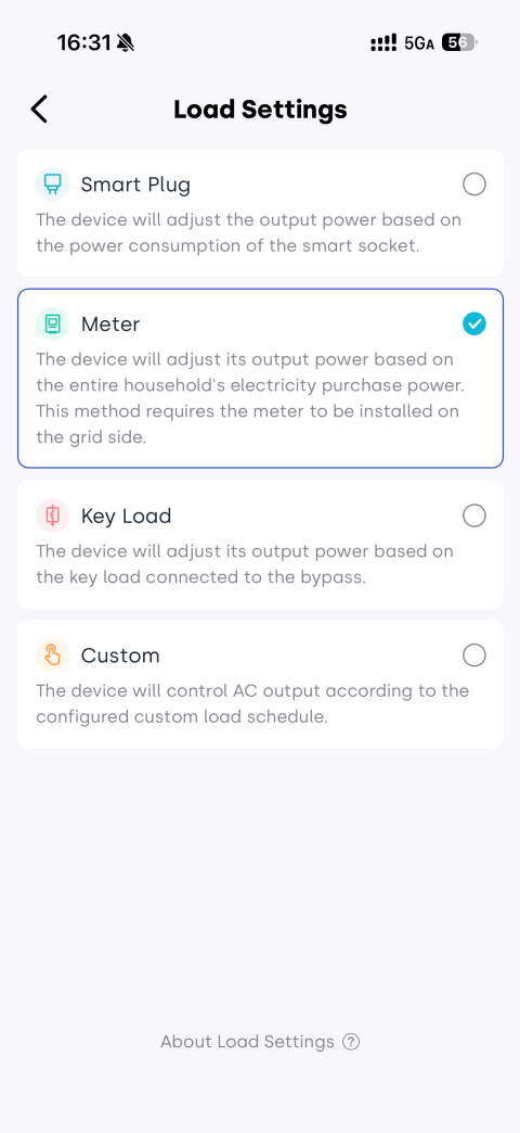
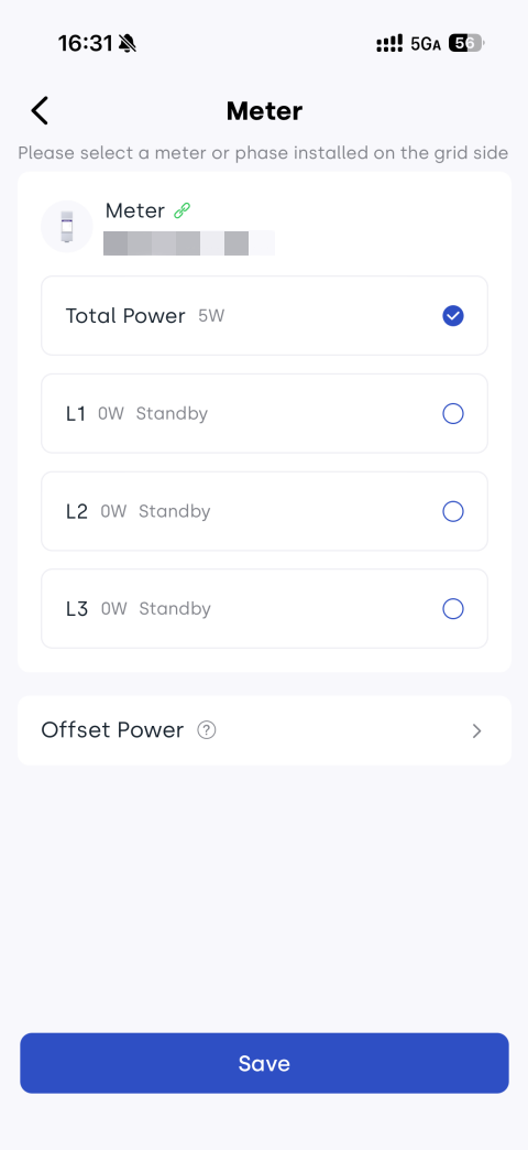
If you want the micro storage system to automatically adjust its operating state based on load conditions, you can select the actual load CT phase as the reference source in Load Settings > Meter.
5. How to Check Your Configuration
After setup, verify the configuration through actual system behavior:
- When PV is generating power, PV power should be positive.
- When consuming grid power, the system should show grid import.
- When the battery is charging, charging power should be displayed.
- When loads are turned on, the corresponding consumption power should increase.
If abnormal values or reversed directions occur, check the following step by step:
- Whether CTs are installed in the correct positions
- Whether CT installation direction is correct
- Whether CT configuration in the app matches the actual setup
- Whether CTs are properly clamped and fully closed