Battery SOC Balancing
1. What Is SOC Balancing
SOC (State of Charge) represents the battery charge level as a percentage.
When multiple battery packs are connected to the micro energy storage device, differences in usage time, temperature, or load conditions may gradually cause the SOC of each battery pack to diverge — even if the batteries are the same model.
At this point, the system automatically performs SOC balancing to keep the battery SOC levels as close as possible.
In simple terms:
Batteries with higher SOC provide more power, while batteries with lower SOC provide less power, gradually reducing the difference over time.
2. Why SOC Balancing Is Important
- Extends battery lifespan by reducing uneven battery cycling
- Improves system stability and operating efficiency
- Enhances safety by reducing risks such as overheating or battery damage
3. Why SOC Imbalance Happens
Even battery packs of the same model cannot be perfectly identical.
Common causes include:
- Small differences in battery capacity or internal resistance from manufacturing
- Different power loads during operation, resulting in different charge/discharge rates
- Mixed use of old and new batteries with different aging levels
- The device itself has some standby power consumption, and standby power may be supplied unevenly by different batteries
- At low power or low current conditions, SOC calculation accuracy decreases, which can accumulate over time
- System operating strategies, such as prioritizing certain batteries for discharge or recharge
Over time, these small differences gradually accumulate and eventually appear as SOC imbalance.
4. Problems with Traditional Battery Connections
In traditional energy storage systems, multiple battery packs are usually connected in series, parallel, or a combination of both.
In this structure, batteries are directly connected to each other, so the system requires a high level of battery consistency.
Series Connection
In a series connection, the overall system performance is limited by the weakest battery.
For example, if one battery has lower capacity or is more heavily aged, it will reach full charge or full discharge earlier than the others.
When this happens, the entire system must stop charging or discharging in advance.
Parallel Connection
In a parallel connection, if there is a voltage difference between batteries:
- The battery with higher SOC will automatically discharge into the lower-SOC battery.
- Internal circulating current will occur between batteries.
This circulating current can cause:
- Additional heat generation
- Energy loss
- Faster battery aging
5. How DCDC Solves These Problems
The micro energy storage device uses a DCDC architecture.
Each battery pack is connected to the system through an independent DCDC module.
You can think of it as giving each battery its own “smart power regulator,” so batteries no longer directly affect one another.
Compared with traditional direct series/parallel connections:
| Traditional Connection | DCDC Architecture |
|---|---|
| Batteries directly connected | Batteries connected independently |
| High battery consistency required | Lower dependency on battery consistency |
| Batteries easily affect each other | Batteries are electrically isolated |
| Difficult to precisely allocate power | Power can be independently adjusted |
| Difficult to mix old and new batteries | Better compatibility with batteries in different conditions |
As a result, under a DCDC architecture:
- Some SOC difference between batteries is acceptable
- The system automatically adjusts power distribution so that SOC levels gradually move toward balance during operation
6. How SOC Balancing Works
The system automatically balances batteries using built-in DCDC modules and EMS (Energy Management System).
The EMS dynamically adjusts charging and discharging power based on the SOC difference between batteries:
- Batteries with higher SOC discharge more or charge less
- Batteries with lower SOC discharge less or receive more charging power
This allows the SOC difference to gradually decrease over time.
During normal operation, the system allows a certain SOC difference between batteries. Typically, the SOC difference remains within approximately 3% to 15%.
Example:
- Battery Pack 1: SOC 80%
- Battery Pack 2: SOC 40%
- Load: 900W
The EMS may distribute power as follows:
- Battery Pack 1 (higher SOC): discharges about 600W
- Battery Pack 2 (lower SOC): discharges about 300W
Over time, the SOC gap gradually decreases until the batteries become more balanced.
7. SOC Balancing at Low Battery Levels
When the overall battery level is low, the system prioritizes safety and essential power supply.
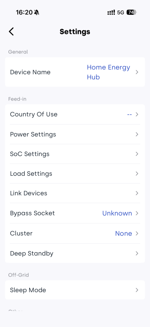
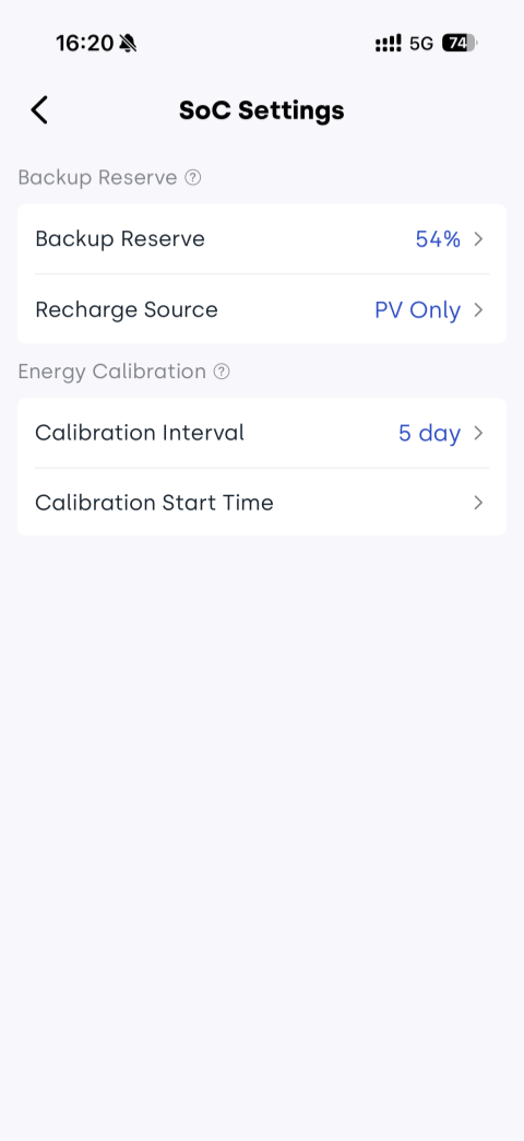
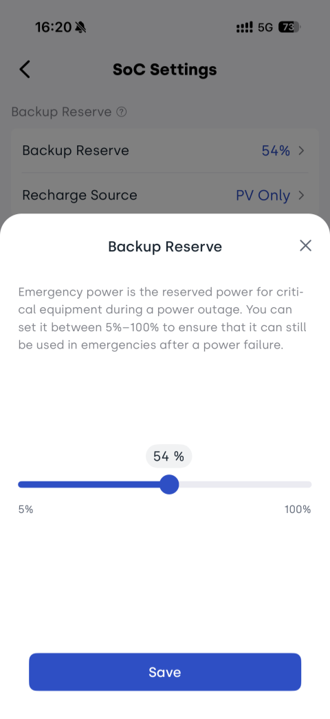
How to View / Configure Backup Reserve
App navigation path:
Device Page → Select Device → Tap ![]() → SoC Settings → Backup Reserve (5%–100%)
→ SoC Settings → Backup Reserve (5%–100%)
7.1 Discharging
- When a battery pack reaches the configured Backup Reserve level, it stops discharging and enters standby mode.
- Other battery packs with SOC above the Backup Reserve level continue supplying power.
7.2 Charging
◽ With PV Available (PV / PV+AC)
All battery packs charge simultaneously.
◽ AC Charging Only
| EMS Version | Behavior |
|---|---|
| Below 1.01.05 | When total SOC is below the Backup Reserve level, all battery packs charge together. Charging stops once the total SOC reaches the Backup Reserve level. |
| 1.01.05 or later | When total SOC is below the Backup Reserve level, the system prioritizes charging battery packs below the Backup Reserve level. Charging stops once the total SOC reaches the Backup Reserve level. |
📌 For detailed recharge behavior, see: Backup Charging Logic
7.3 Standby
◽ Main Unit Power Consumption
Whether the main unit includes an AC auxiliary power module affects where standby power is sourced from. This information will be displayed in the App in future versions.
Deep standby power consumption of the main unit is approximately 6W:
- Without an auxiliary power module: powered by the internal battery, causing the main unit SOC to decrease faster than the battery packs
- With an auxiliary power module: powered by the auxiliary module (which draws power from the grid when connected), reducing battery consumption
◽ Battery Pack Power Consumption
Approximately 2W, always powered by the battery pack itself.
📌 For more details, see: Standby Power Consumption